Principals of CNC
Basic length unit (BLU):
Each BLU unit corresponds to the position resolution of the axis of motion.
For example
1 BLU=0.0001
it means that the axis will move 0.0001 for every one electrical pulse received by the motor.The BLU is also referred to as Bit
Pulse=BLU=Bit
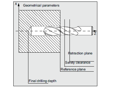
Point to point system:
Point to point system are those that move the tool or workpiece from one point to another and then the tool performs the required task.
Upon the completion,the tool(or workpiece) move's to the next position and the cycle is prepared

The simple example for this type of system is a drilling machine.
Continuous path system:
These systems provide continuous path such that tool can perform while the axis are moving,enabling the system to generate angular surface, two-dimensional curves,or three-dimensional contours.
Example is a milling machine where such tasks are accomplished.


Incremental and Absolute system:
CNC system are further divided into incremental and Absolute system.
Absolute system:
With absolute dimensioning data refers to the zero point of the origin.

All positions are referred main origin
P1
X20 y35
P2
X50 Y60
P3
X70 Y20
X,Y indicate axis
Incremental Dimensions:
With incremental dimensioning data refers to the last point to the next point incrementally.it means every positions are to be calculated from the present tool's position

X20 Y35
P2
X30 Y20
P3
X20 Y-35
Open loop closed system:
The open loop control system means there is no feed back and uses stepping motors for driving the lead screw
A stepping motor is a device whose out put shaft rotates through a fixed angle in response to an input pulse.The accuracy of the system depends on the motor's
ability to step through the exact number. The frequency of the stepping motor depends on the
load torque. The higher the load torque, lower would be the frequency . Excessive load torque
may occur in motors due to the cutting forces in machine tools. Hence this system is more
suitable for cases where the tool force does not exist

pulse causes the motor to rotate a fraction of one revolution. The fraction is expressed in
terms of the step angle, oc, given by
a = 360/N, degrees where N = number of pulses required for one revolution
If the motor receives "n" number of pulses then the total angle,
In terms of the number of revolutions, it would be (n/N)
If there is a 1 :1 gear ratio between the motor and the leadscrew, then the leadscrew has (n/N)
revolutions . If the pitch of leadscrew is p (in/rev), then the distance traveled axially, say x,
can be used to achieve a specified x-increment in a point-to-point system.The pulse frequency, f, in pulses/sec determines the travel speed of the tool or the workpiece .
60 f = N (RPM) where N = number of pulses per revolution,
RPM = RPM of the lead screw
The travel speed, V, is then given by V = p (RPM) where p pitch in in/rev
Closed loop control system:
Closed loop control system are appropriate when there is a force resisting the movement of the tool and work piece.milling and turning are typically example for in this system.
The DC servo motor and feedback device are used to ensure the desired position is achieved.the feedback sensor used is an optional encoder.the encoder consists of a light source,a photo detector and disk containing a series of slots.The encoder is
connected to the leadscrew . As the screw turns, the slots cause the light to be seen by thephotodetector as a series of flashs which are converted into an equivalent series of electrical
pulses which are then used to characterize the position and the speed. The equations remain
essentially the same as open-loop except that the angle between the slots in the disk is the
step angle, a.
Both the input to the control loop and the feedback signals are a sequence of pulses, each
pulse representing a BLU unit. The two sequences are correlated by a comparator and gives
a signal, by means of a digital-to-analog converter, (a signal representing the position error),
to operate the drive motor (DC servomotor) .


Comments
Post a Comment